Recommended Products
Rectifiers for Electropolishing
Our recommended units for electropolishing applications — precision IGBT switchmode rectifiers delivering the clean, stable DC that mirror-finish surfaces demand.
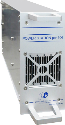
PE 3000 Series
10A – 3,000A · 0–24V / 0–48V DC
Compact modular IGBT switchmode rectifier with <1% ripple, ideal for electropolishing lines requiring precise current-density control. Constant-current mode automatically compensates for bath temperature and conductivity changes. RS485/TCP-IP communication and programmable ramp-up for flash-attack prevention.
Primary Pick
View Product →
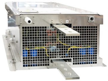
PE 4000 Series
20A – 2,200A+ · Parallelable to any capacity
Flagship high-current rectifier for large-scale electropolishing production. PROFIBUS and TCP/IP networking for full automation integration. Parallelable without limit for oversized tank installations. Full digital control via pe280 with programmable multi-step current profiles.
Primary Pick
View Product →