Recommended Products
Rectifiers for Anodising
Scroll through our recommended units for anodising applications — from compact bench systems to full production-line colour anodising installations.
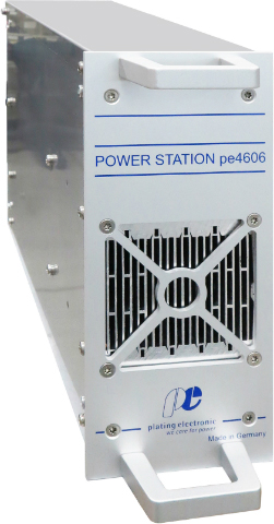
PE 3000 + pe8705 Colour Control
10A – 3,000A · 0–24V / 0–48V DC
The optimal combination for colour anodising. The PE 3000 delivers <1% ripple IGBT power while the pe8705 controller automates multi-step colour sequences — programming current, timing, and polarity for each colour step. Produces repeatable bronze, black, and champagne finishes batch after batch.
Primary Pick
View Product →
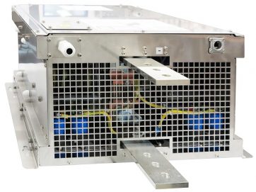
PE 4000 Series
20A – 2,200A+ · Parallelable to any capacity
For large-format hard anodising lines requiring high current and wide voltage range. PROFIBUS and TCP/IP networking, full digital control via pe280, and seamless CC/CV crossover for managing growing oxide resistance. Ideal for aerospace and defence hard-coat anodising.
Primary Pick
View Product →
PE 1000 Series
50A – 600A · 0–18V DC
Compact IGBT rectifier for smaller anodising operations, job shops, and laboratory process development. Same <1% ripple quality as the larger units. RS485 communication and amp-hour totalisation for oxide thickness control.
Also Suitable
View Product →