Recommended Products
Rectifiers for Electroplating
Scroll through our recommended units for electroplating applications — from compact bench units to full production-line systems.
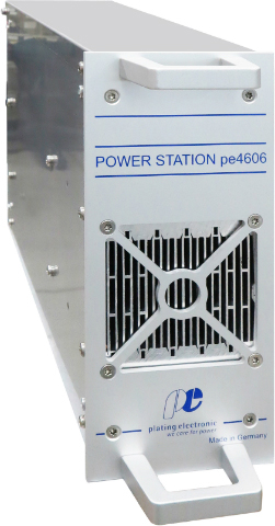
PE 3000 Series
10A – 3,000A · 0–24V / 0–48V DC
The workhorse of European plating shops. Compact modular IGBT switchmode rectifier with <1% ripple, RS485/TCP-IP communication, and amp-hour counter as standard. Ideal for rack and barrel nickel, zinc, and copper lines.
Primary Pick
View Product →
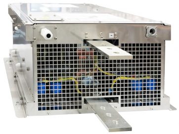
PE 4000 Series
20A – 2,200A+ · Parallelable to any capacity
Flagship high-current rectifier for heavy-duty production lines. PROFIBUS and TCP/IP networking, parallelable without limit, field-proven at a major Australian steel manufacturer's large-scale galvanising installation. Full digital control via pe280.
Primary Pick
View Product →
PE 1000 Series
50A – 600A · 0–18V DC
Entry-level IGBT switchmode rectifier for smaller plating operations, laboratory R&D lines, and job shops. Same <1% ripple quality as the larger units in a compact footprint. RS485 communication and amp-hour totalisation.
Also Suitable
View Product →
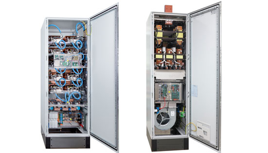
Pulse Reverse Systems
Custom waveform · 1–16 pulse steps
For advanced plating applications requiring periodic reverse current — via-fill PCB plating, connector gold plating, and alloy deposition. Programmable pulse frequency, duty cycle, and reverse amplitude under full digital control.
Specialist
View Product →